TEST ON DIE-CAST ROTORS
This test, simple, practical and effective has been performed by RISATTI INSTRUMENTS since 1975, and it permits the immediate detection of the main faults on die cast rotors.
Before the explanation of the test principles, we would like to point out the importance of this test for the technical assistance and for the repair sector and the use in laboratories for the research on sample rotors.
In fact, it is quite common that the burning of an electrical motor is due to a fault on the die-cast rotor. The fault causes a lower efficiency of the motor with consequent major heating on the rotor winding that can cause the complete destruction of the motor.
It is extremely useful to have available a quick and secure system to test the rotor before having to rewind the entire stator. It would be useless to substitute or repair the stator without the substitution of the damaged rotor.
A – OPERATING PRINCIPLE
The O4/BPR pick-up, using built-in permanent magnet, generates a continuous flux between its polar expansions.
Rotating the rotor under test, its rods go through this flux and became site for an inducted current that is inversely proportional to their ohmic resistance: the lower is the resistance (absence of defects) the higher is the current circulating.
This current generates a reverse flux proportional to its intensity that, using particular receiving windings, is transformed in electrical signals similar to a sinusoid for each rod explored. These signals, properly amplified, are shown on the display of the machine.
The constant amplitude of all signals displayed indicates absence of defects, whilst a reduced amplitude of one or more signals, or the complete absence, indicates defects due to different reasons that will be explained later on.
B – POSITIONING AND REGULATION OF THE PICK-UP O4/BPR
The rotor to be tested must be rotated using a suitable mechanical tool (e.g. a lathe), with a sufficient speed for our machines to show all the rotor’s rods on the display.
The O4/BPR pick-up must be positioned, using the regulation screws P1 to a distance – D – from the rotor external surface. The distance D must be 2 to 3 mm for closed rotors or 3 to 5 mm for open rotors (the signal is stronger).
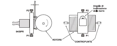
Unscrewing the handle P2, the pick-up can rotate on its own axis to permit the alignment of the polar expansions to the rotor’s rods, allowing in this way to evaluate even the inclination angle of the rods.
This is achieved, when the amplitude of the curve on the display, during the regulation of the pickup, reaches the maximum level.
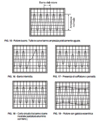
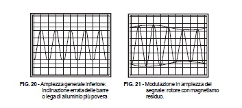
C – EXAMINATION OF THE CURVES
Below there are some examples of the defects that can be detected. The curves can help in the evaluation of the test result, but it always has to be kept in mind that often, various defects are combined together and generate curves that are slightly different from the curves shown below.
D – VISUALISATION OF THE CURVES ON THE DISPLAY
To obtain a better definition, the curves relevant to the same rotor have been divided into three consecutive screens.
To guarantee a correct visualisation of the entire curve relevant to a rotor, and in order to define the optimal “ t ” value to be given to each divisions in each screen, the following relation is taken into consideration:
![]()
Where:
t =time in milliseconds for each division
n =rotor turns number in a minute (RPM)
Example: Rotation speed n= 500 turns/minute
![]()
The 5 milliseconds per division value is chosen because it allows a secure visualisation of all the rotor.
It is not always possible to know all the values mentioned above, therefore, it is necessary to give an estimation and then verifying the data with the obtained test result.
It is always possible to use a simple method to verify if all the rotor rods are visualised; taking as granted that does not exist a rotor that is perfect, it is possible to focus the attention on the repetition of the same little defect. Taking the defect as a marking point, set it to the far left side of the display of the first screen (relevant to the rotor under test), and then set the same defect at the far right side of the display on the third screen relevant to the same rotor.