MEASUREMENT OF THE OHMIC RESISTANCE
It is really important to measure the ohmic resistance of a winding. This not only to verify its continuity, but also to determine if the diameter of used the wire is correct (to detect the number of turns the SURGE test is much more precise), to determine the balance between the phases (for three-phases windings) and finally, to detect the temperature rise, due to the operating conditions. For the various methodologies, refer to the user manual of our machines, but we would like to point out some of the main functions of this kind of measurement.
A – 4 WIRES READING
On all instruments of our production, the ohmic resistance is read using the method known as “4 wires”.
This method consists in connecting each terminal of the winding to be tested with 2 different contacts, insulated between each other, that contact the winding in 2 different points.
This method avoids the measurement to be influenced by false contacts, contacts oxidation, contact resistance of the switching relays, length and diameter of the connection cables, etc.
Below the “4 wires” method schematics, compared to the “2 wires” method.
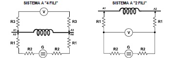
Where:
A = Contact points
G = Constant current generator
V = Voltmeter (for voltage reading)
R1 = Contact resistance of the supply terminal of the winding under test
R2 = Resistances created by the relay contacts of the switching system and to the length of the connection cables
R3 = Contact resistances (circuit for voltage reading)
The constant current generator, independently of the total value of resistance of the circuit, generates a constant and precise pre-set current.
As a consequence of the current flowing through the circuit, at the ends of each single resistance a voltage drop is present.
When comparing the 2 schematics, the behaviour of the voltmeter is immediately evident.
In the “2 wires” schematic, the voltmeter reading is influenced by voltage drop on R1, whilst using the “4 wires” method the voltmeter is influenced by R3.
The difference between the two methods is the following: the voltage drop on R1 can be really sensible because the test current flows through R1; the voltage drop on R3 is really limited because due to the voltmeter high impedance, in the reading circuit there is no current flowing.
In this case, the voltage value read by the voltmeter corresponds exactly to the voltage drop value on the resistance to be tested.
It is also evident that when the R1 and R2 values are over certain levels (ex. cables completely oxidised), the current generator will not be able to generate the pre-set current and therefore the voltage reading will be wrong or even impossible.
B – COMPENSATION OF AMBIENT TEMPERATURE
All the instruments of our production are supplied (standard or optionally) with this useful function; it is known that temperature variations on a copper winding can determine a ohmic resistance variation (about 0,4% for each grade centigrade).
In this way, a 10°C variation can cause about a 4% variation of the original value: this variation has to be taken into consideration.
When the system is supplied with automatic room temperature variations compensation, every reading shows the value correspondent to the value at 20°C (or other under request)
This is possible because a probe, positioned on the back of the instrument, is used to read and displays the room temperature. Having this information, the software of the instrument is capable to correct the value read on the device tested.
In any case, it is necessary to take some precautions: give time to the probe to get adjusted to the room temperature, especially when the instrument is moved from one room to the another or when it comes from outdoor. Always make sure that the windings to be tested are at room temperature or it is necessary to give them time to adjust to room temperature before performing any measurements..
C – VERIFICATION OF THE RESISTIVE BALANCEMENT BETWEEN THE PHASES
On the three-phase windings, it is important to verify that the 3 resistance values correspondent to the three phases are within a limited tolerance between one another.
Our machines are supplied with this functionality. When it is activated it allows to define 2 tolerance values: one for the absolute value of the three windings and the other for the tolerance between one another. Both the tolerances have programmable thresholds and can generate an automatic GO – NO GO test result.
Practically, within the 3 measured values, the lower and the higher are taken and it is verified if the interval (percent) is within the set limits.
D – EVALUTATION OF THE TEMPERATURE RISE IN A WINDING
Another important function given by our machinesis the possibility to evaluate the ΔT of any winding.
This is extremely useful in order to evaluate if the motor under test has some operating anomalies (e.g. a phase missing, contacts for motor safety burnt, etc.). The winding resistance is memorised when the motor is in stand-by (cold measurement). Then the motor is started and after a specified time the new resistance value is read (hot measurement); the instrument will automatically calculate and display the temperature rise in °C.
For the three-phases windings, with the motor in stand-by (cold measurement), the unbalance between the phases is measured (as described in the previous paragraph) and then, with the motor working (hot measurement), after a specified period of time the unbalance and the ΔT relevant to each single phase..
The formula used is the following:
![]()
Where:
R1 = Resistance to cold temperature
R2 = Resistance to hot temperature
acu= Copper temperature coefficient