DETECTION OF IRON LOSSES
TYPE N1/C.12
In some Countries, particularly attentive to energy saving, some specific rules impose that the motor output should be clearly indicated on the motor plate itself.
It is clear that, even a very few watt saving multiplied per millions of motors working, result in an energy amount saving, which could be very important.
In an electric motor, the more iron and copper losses are reduced, the higher is the output. In order to achieve the best result in making a high output product, which could be also cheap, the cause and the extent of these losses should be kept under control.
As far as copper losses are concerned, they are relatively simple to be detected, and so corrected. On the other hand, iron losses may be brought about by several different and concurrent causes, both in the stator and in the rotor, and so it is much more difficult to find and test them.
The equipment that we have projected and realised, permits to make a comparative test of iron losses in stators and rotors, against a sample motor.
Magnetic losses in systems working in an A.C. are composed by hysteretic and parasitic current losses, and are roughly proportional to the square of the magnetic circuit flux density.
In the purpose of improving the electric device efficiency, the magnetic losses should be kept at a minimum, and to do this, it is necessary to know all the elements influencing such losses. Our N1/C.12 testing equipment permits to find out the level of magnetic losses both on assembled and wound stator packs, during each step of the production cycle.
As a matter of fact, the magnetic losses in the sheet metal, used for the motor, are declared by the Producer, and easily tested through some recognized systems in compliance with specific rules (i.e. Epstein Yoke); but the losses caused by the manufacture for obtaining the final stator are much more numerous, and not so easy to be detected.
Our system, through the comparison with a sample stator, allows to test the losses increase during the various production phases and to find out their origin, such as:
- Losses caused by trimming, because of the breaking of the crystalline system composing the sheet.
- Losses due to short-circuit among the stator core laminations, owing to the flash caused by the trimming, especially because the dies are not sharp enough.
- Losses due to the various packing systems, such as: clamping, riveting, nailing, welding, buttoning, etc.
- The core laminations, which are not insulated enough in surface, and so the parasitic currents among the laminations increase.
- Efficiency test of the stator thermal treatment, in order to make the crystal orientation easier, and to improve insulation among the laminations.
This new N1/C.12, realised with a unique equipment, allows laboratory and production tests, upon a possible loading and unloading of the stator.
The standard equipment admits a wide range of stators: from a minimum hole of 50mm, external diameter of 250mm and height of 200mm. Specific devices are realised for particular products or specific applications.
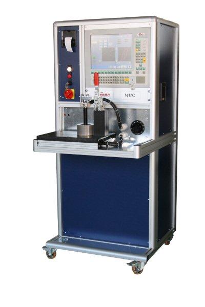
(INDICATIVE PICTURE OF THE SYSTEM)
Essentially, our system is able to detect both the watt losses of the complete stator pack at different induction values, and display the hysteresis curve, in order to evaluate its saturation degree.
Let us consider the reasons why we have decided to project and realize a system to detect iron losses. As already stated in our introduction, in order to keep the quality of magnetic material employed under control, there are laboratory tests, specific for quantity estimation of iron losses, which normally are due to magnetic hysteresis and to parasitic currents.
One of the best methods to determine the above causes is called ‘Epstein Yoke’. According to this method, some samples of magnetic materials should be prepared, with a standardized form and an assembly procedure. But this operation requires quite a long time for preparing samples, and, therefore, it is not suitable for tests on production lines.
In such cases, in fact, the testing system is expected to give measurement results in real time, in order to maintain the production quality under control.
Considering this, we elaborated the technical specifications that have to be satisfied while projecting and constructing the testing system.
The first requirement to satisfy is the sample matter: they should consist in some pieces taken from production, and not purposely prepared.
The second important requirement is the easiness and quickness of the test and therefore the electrical and mechanical coupling with the detection systems of the testing equipment. Like all the testing and control systems, the equipment will provide a series of measures as output, in order to allow a quantitative analysis of the device under test. Once that the production tolerance has been established the equipment can be used as GO/ NO GO control system.
The system should not be employed only for production controls, but also as laboratory instrument. For this reason, together with the instrument for iron losses detection, a system for acquiring the curve of magnetic hysteresis has been included with related graphic representation of the hysteresis cycle of the testing piece.
Moreover, in reference to this instruments, usable also in laboratory, we briefly summarise the theoretical principles of the machine functioning, which relate to the Epstain equipment.
A stabilised and adjustable sinusoidal voltage generator supplies a primary inductor winding. The second winding (secondary) has 2 possibilities. To uses the coil, already inserted in the equipment, so that the system is easier to connect (above all in production tests) or to wind a certain number of coils in a slot (5 or 10) to improve precision (for laboratory measures) and connect them to the proper clamps in the front.
This winding will be then connected to the appropriate plug on the measure system for the reading of the secondary induced voltage, which will result proportional to the flux density inside the nucleus.
E = 2*P*f *F N /√2
Where:
f = is the frequency of the voltage pulsation of the supply
F = is the flux
N = is the number of the secondary coils
The particular realisation of the control electronic parts, allows the laboratory and production use. For high productions, it is necessary to realise a pneumatic equipment, according to the specific application.
Therefore, being known the transversal section of the lamellar package, the flux density will be:
B = F/S B =( E */√2) / 2*P*f F *S
Being known the max induction value at which the stator should work, the system software, on the basis of the above principles, will be able to exactly define the secondary voltage value, and consequently provide the control circuits of power supply voltage, with reference value necessary to obtain the required flux density.
An electronic watt meter connected with the amperometric circuits on the primary power supply of the system under test, and the volt metric circuits connected with the inducted winding will measure the iron losses.
In short: Pw = E2* I1*cos(E2 ^ I1)
Therefore, being known the winding ratio secondary/primary, the previous relations becomes:
Pf =(N2/N1) *E1* I1*cos(E2 ^ I1)
Representing the power transferred to the nucleus and, so corresponding to the sum of the losses by hysteresis and by parasitic currents.
By means of a system for data acquisition and digitizing, the system software also provides a graphic display of both values of inducted voltage and magnetizing current, after a subsequent elaboration of mathematic integration on the wave form of the inducted voltage and of the magnetizing curve or magnetic hysteresis cycle.
In this way, we supply a useful mean for evaluating the magnetic saturation degree of the nucleus, and, at the same time, having a visual quantification of the losses for magnetic hysteresis.
After making the measurements on the sample specimen, you have the possibility to store the system setting; this will permit you to perform the test with different specimen, by keeping unchanged the conditions of energizing the d.u.t., in order to have an easy comparison between some specimen of the same type and one sample specimen (master).
This possibility allows the use of the system in its second working modality, particularly intended to perform tests in a production control context.
Test screen-shot
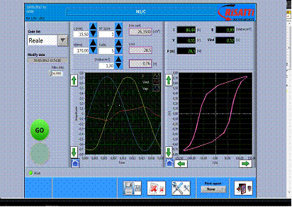
In the following picture you will find, as an example, the main screen of the N1/C system.
The machine can do semi-automatic tests, it provides voltage, current and flux values as results. Besides, it offers a graphic indication of the hysteresis cycle.
The comparison between the measured values and the re-set ones allows the price evaluation. The setting doesn’t require additional windings and no other action on the stator: this latter has to be simply positioned on the machine plain and the clamp has to be closed.
The machine applies current (manually settable acting on a Variac voltage generator) and it measures the generated current, the voltage on the first circuit (the clamp), the voltage and the dynamic phase on the second circuit.
All necessary calculations are realized by the management software; the graph on the left side indicates the voltage, current and induced voltage values.
On the right there is the hysteresis curve, defined according to the realized measures.
The whole graph can self reduce or manually zoomed.
Besides, it is possible to store the results for this stator; the machine is ready to indicate whether the sample is under test and suitable to the stored results of the sample.
The picture above indicates a stator sample of medium dimensions: on the top left there are the limit values such as:
- Length and height in mm
- N. of coils in the secondary. Important: the machine can work with the incorporated secondary (a coil) or the secondary can be used up to 10 coils.
- The stored and required B
- The acceptability limit in percentage
- Acceptable losses (W)
Always on the top left, there the results of:
- The section calculation (cmq)
- The value of the hypotized induced voltage
The operator can apply power to the sample by rotating the Variac control until the induced voltage value (Vin) matches with the pre-calculated hypnotized one (V).
Now, if the field and leakage values enter into acceptable limits, the GO light will switch on; otherwise we will have a NO GO indication.

The picture above shows a test on a small stator, H=75mm and L=15mm; it has been tested with the incorporated secondary (1 coil) and the reference sector is 1.3 weber/m2
Machines indicate iron losses of 10,6 watts and an induced voltage of 0,34V: as you can see, the given voltage of 62.15 A, @ 0,34 V leads to a 1.3 weber/m2 sector and leakages of 10.6W.
N1/C electromechanical realisation
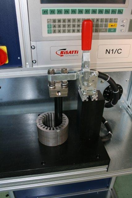
The picture shows the new instrument; by opening the level block, it is possible to insert and remove the DUT. No external windings are necessary. However, you can use them through a winding of maximum 10 coils connected to proper clamps.
Finally, we would like to underline that, our system does not substitute the classical methods used to determine slot magnetic characteristics for electric machines. On the contrary, it intends to satisfy the needs of electric machine producers, who want to easily check the quality during the semi-finished production. In other words, this instrument wants to maintain under control the quality of used magnetic materials and above all, of the finished piece, evaluating the accuracy of single phases (trimming, assembly, intra-slot insulation, etc.). Thanks to the easiness and rapidity of controls, the N1/C will contribute to elevate production qualitative standards and obtain a considerable electric energy saving.